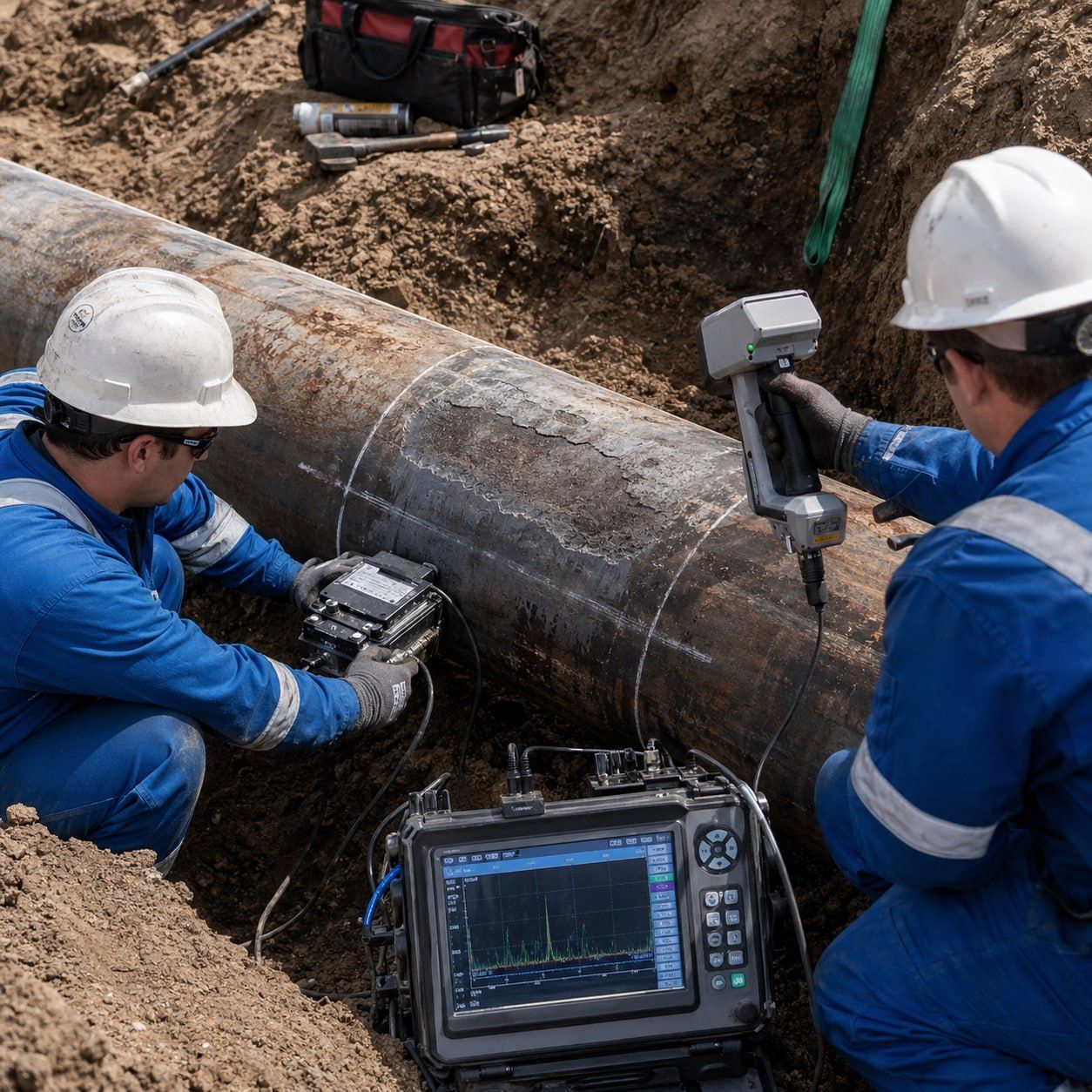

Pipeline integrity is not only about detecting anomalies from ILI, UT, MFL, EMAT, PAUT, or field excavation.
The real engineering question is:
What type of damage is it, what failure mode can it create, how fast can it grow, and can the pipeline safely continue operating?
A pipeline defect is never just a “feature” in a report.
It may be metal loss, cracking, denting, weld-related degradation, ground movement, lamination, or a combined anomaly.
Each one fails differently.
Each one needs a different assessment method.
1️⃣ Metal Loss Assessment
Metal loss is usually the most common pipeline threat, but it is also one of the most misinterpreted.
The mistake is treating every metal loss feature as simple corrosion depth.
A proper assessment must define the type of metal loss first.
Common metal loss damage types include:
Internal corrosion
Bottom-of-line corrosion due to water hold-up
Under-deposit corrosion
CO₂ corrosion
H₂S/sour corrosion
MIC-related pitting
Erosion-corrosion at high velocity or turbulence zones
External corrosion
Coating damage corrosion
Shielded CP corrosion under disbonded coating
Soil-side corrosion
Corrosion at supports or casing crossings
External corrosion at holidays in coating
Localized corrosion
Isolated pits
Clustered pitting
Axial grooves
Circumferential grooves
Gouge-like metal loss
Narrow deep pitting with small surface opening
Weld-associated corrosion
Corrosion at girth welds
Corrosion near heat-affected zones
Selective seam weld corrosion, SSWC
Corrosion interacting with the longitudinal seam weld
Metal loss assessment is not only about depth.
It must consider:
Defect depth
Defect length
Width and orientation
Axial vs circumferential extent
Interaction between adjacent pits
Remaining ligament
MAOP / operating pressure
Pipe diameter and wall thickness
Pipe grade and toughness
Corrosion growth rate
Location relative to welds
Consequence of failure
A 40% isolated pit and a 40% long axial groove do not carry the same risk.
For metal loss, common assessment approaches include ASME B31G, Modified B31G, RSTRENG, DNV-RP-F101, and API 579 / ASME FFS-1, depending on operator procedure, data quality, and defect geometry.
But one rule is critical:
Metal loss assessment calculates remaining strength.
It does not assess crack-like flaws.
2️⃣ Crack Assessment
Cracks are completely different from corrosion.
Metal loss reduces wall thickness.
A crack creates a sharp flaw with high stress concentration at the crack tip.
That is why crack assessment requires fracture mechanics, not corrosion formulas.
Main pipeline crack types include:
Stress Corrosion Cracking, SCC
High-pH SCC
Near-neutral-pH SCC
Usually external
Often appears as axial crack colonies
Common under disbonded coating with moisture and CP shielding
Fatigue cracking
Driven by pressure cycling
Initiates at weld toes, inclusions, notches, or surface defects
Grows slowly at first, then accelerates as crack depth increases
Seam weld cracking
Hook cracks
Lack of fusion
Cold weld defects
ERW seam defects
Flash weld defects
Crack-like flaws along the longitudinal seam
This is especially critical because the longitudinal seam lies in the highest hoop stress direction.
Girth weld cracking
Root cracks
Toe cracks
Lack of fusion
Hydrogen-assisted cracking
Cracks driven by ground movement or bending strain
Hydrogen-assisted cracking
HIC
SOHIC
HAZ cracking
Sour service cracking
Hard weld zone cracking
Corrosion-fatigue cracking
Corrosion pit acts as a crack starter
Cyclic pressure drives crack propagation
Environment reduces fatigue resistance
For cracks, the key parameters are:
Crack depth
Crack length
Crack orientation
Crack location
Stress intensity factor
Material fracture toughness
Pressure cycling
Residual stress
Environment
Crack growth rate
The real question is not:
“Is the crack visible?”
The real question is:
How close is the crack to fracture instability?
For crack-like flaws, the suitable route is fracture mechanics-based assessment such as API 579 Part 9, BS 7910, or operator-approved pipeline crack assessment procedures.
3️⃣ Dent Assessment
Dents are not only shape defects.
A dent changes pipe geometry, introduces local strain, and can create high stress concentration.
The most important step is dent characterization.
Common dent types include:
Plain smooth dent
No metal loss
No gouge
No cracking
No weld interaction
Usually lowest risk if strain is acceptable
Kinked dent
Sharp curvature
High local strain
Higher crack initiation risk
Rock dent
Caused by external mechanical contact
Often constrained by soil or rock
May include coating damage and external corrosion
Unconstrained dent
Dent spring-back occurs after load removal
Fatigue behavior depends on pressure cycling
Constrained dent
External object remains in contact with the pipe
Continued local loading may drive fatigue or cracking
Dent on girth weld
High risk due to weld geometry, residual stress, and possible weld defects
Dent on seam weld
Very high risk because the dent interacts with the longitudinal seam stress path
Dent with gouge
One of the most severe combinations
Gouge creates a sharp notch
Dent adds strain concentration
Dent with metal loss
Reduced wall thickness + local strain
Remaining strength and fatigue must both be considered
Dent with crack
Critical condition
Requires immediate engineering assessment
API 1183 is the key reference for structured dent management, but the engineering principle is simple:
A dent is a strain problem first.
If combined with gouging, cracking, corrosion, or weld interaction, it becomes a fracture and fatigue problem.
The most dangerous dent is not always the deepest one.
The most dangerous dent is the one with sharp curvature, weld interaction, metal loss, gouging, or cyclic loading.
4️⃣ Combined Anomalies
Combined anomalies are where many assessments become dangerous.
A defect may pass as an isolated feature but fail when interaction is considered.
Common combined damage types include:
Dent + gouge
Dent + metal loss
Dent + crack
Dent + seam weld
Dent + girth weld
Corrosion + SCC
Pitting + fatigue crack
Metal loss + lamination
Corrosion crossing seam weld
External corrosion under disbonded coating with SCC
Multiple interacting corrosion pits
Gouge with hard spot
Weld defect with cyclic loading
Combined anomalies are dangerous because the failure mechanisms interact.
Metal loss reduces remaining wall.
A dent increases local strain.
A gouge creates a notch.
A crack introduces fracture instability.
A weld adds residual stress and metallurgical discontinuity.
Together, they can create a failure mode that simple screening may not capture.
This is where Level 1 screening may be insufficient and escalation to detailed assessment is often required.
5️⃣ Other Pipeline Threats
Not all pipeline threats are pressure-driven corrosion or cracking.
Some are strain-driven, construction-related, or manufacturing-related.
Important threats include:
Geohazards
Landslides
Soil movement
Subsidence
Fault movement
River crossings
Washouts
Slope instability
These create bending and axial strain, not only hoop stress.
Bending strain
Pipe may be safe under pressure but unsafe under external ground movement
Strain-based assessment becomes necessary
Circumferentially oriented defects
Circumferential cracks
Girth weld defects
Axial-load driven flaws
More sensitive to axial stress and bending than pressure alone
Laminations
Mid-wall laminations
Inclusion-related laminations
Laminations interacting with corrosion
Laminations connected to the surface
Hydrogen blisters and stepwise cracking
A lamination may be harmless if isolated and stable.
But if it connects to the surface, interacts with pressure stress, or links with hydrogen damage, it can become critical.
Hard spots
Local hardened areas
Susceptible to cracking
Often linked to manufacturing or welding thermal history
Higher risk in sour or cyclic service
Engineering Takeaway
Pipeline defect assessment is not a checklist.
Each damage type asks a different engineering question:
Metal loss:
How much remaining strength is available?
Cracks:
How close is the flaw to fracture instability?
Dents:
How much strain has been introduced?
Combined anomalies:
Are multiple failure mechanisms interacting?
Geohazards:
What external strain demand is applied to the pipe?
Laminations:
Is the flaw isolated, connected, or interacting with stress and corrosion?
The strongest integrity decisions come from connecting:
Inspection data
Damage mechanism
Failure mode
Growth rate
Material resistance
Operating pressure
Pressure cycling
Environment
Consequence of failure
Pipeline integrity is not about finding anomalies.
It is about understanding which anomaly can become a failure — and when.
#PipelineIntegrity #AssetIntegrity #API1183 #API579 #ASME #B31G #B318S #API570 #Corrosion #CrackAssessment #DentAssessment #SCC #MetalLoss #NDT #MechanicalIntegrity #OilAndGas #ProcessSafety


Leave a Reply