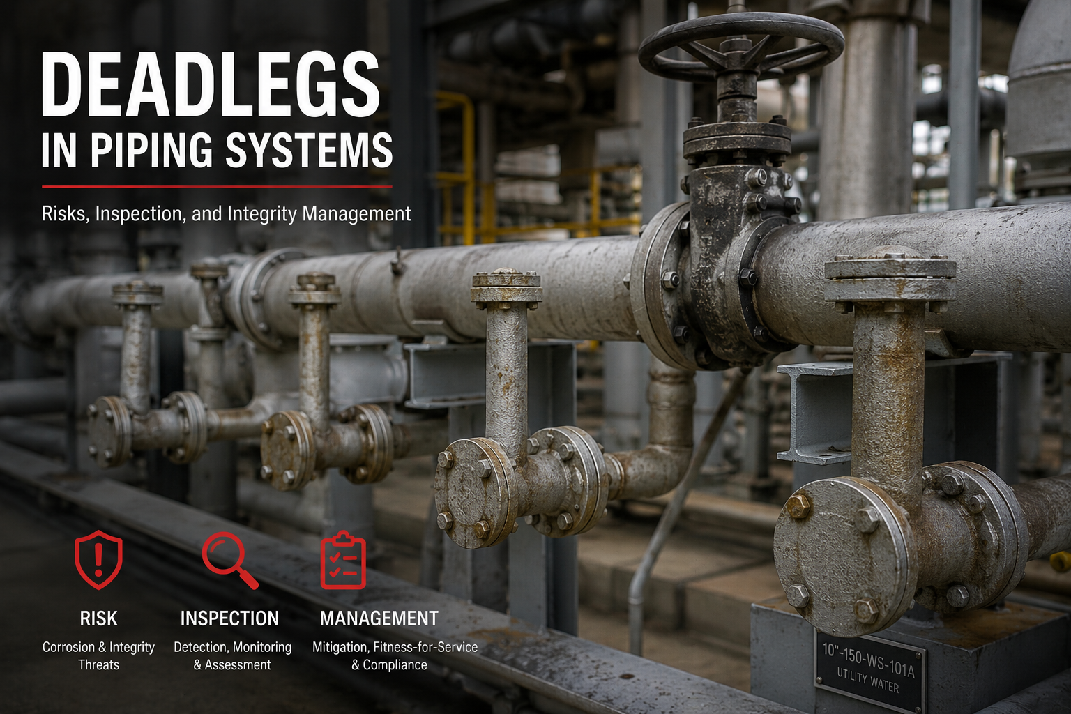

In piping integrity, some of the highest-risk locations are not always the largest lines, the highest-pressure circuits, or the most visible equipment.
Sometimes the problem is a small branch, a blinded connection, a normally closed bypass, a drain, a vent, or an old line that is still connected to the process but no longer flowing.
This is what we call a deadleg.
A deadleg is a section of piping where there is little or no normal flow. It may still be pressurized, still connected to process fluid, and still part of the pressure boundary — but hydraulically, chemically, and thermally, it may behave very differently from the active main line.
That is why deadlegs are not just “inactive piping.”
They are potential localized corrosion traps.
What is a deadleg?
A deadleg is a stagnant or low-flow section of piping connected to an active process system.
It may be:
- Open to the process but not flowing
- Isolated by a normally closed valve
- Blinded or capped at one end
- Connected to instruments or drains
- Connected to a spare item of equipment
- No longer used but still connected to the live system
From an inspection point of view, the key issue is this:
The deadleg may not have the same corrosion rate, temperature, phase behavior, or damage mechanism as the main piping circuit.
The main line may be clean, flowing, and dry.
The deadleg may be stagnant, wet, fouled, acidic, sour, or operating in a completely different temperature range.
Why are deadlegs dangerous?
Deadlegs are dangerous because they create conditions that favor localized damage.
In active piping, velocity, mixing, temperature, and chemistry may remain reasonably controlled. In a deadleg, the situation can be very different.
Inside a deadleg, the following can occur:
- Water drops out and remains trapped
- Solids settle and create under-deposit conditions
- Corrosive species concentrate
- Acidic deposits form
- H₂S and water coexist locally
- Oxygen ingress may occur during shutdown or maintenance
- Bacteria may grow in stagnant water
- A liquid/vapor interface may form
- Temperature may fall into the CUI range even when the main line is outside it
- The stagnant end may become chemically different from the flowing line
This is why a deadleg can corrode faster than the main pipe even though both are connected to the same process system.
A common failure pattern is:
The inspection program monitors the main line → the main line looks acceptable → the deadleg is not adequately inspected → localized corrosion develops → leak occurs at the branch, drain, vent, bypass, or stagnant end.
Where do deadlegs occur?
Deadlegs are common in almost every process plant.
Typical locations include:
- Blinded branches
- Capped branches
- Normally closed bypasses
- Spare pump suction/discharge piping
- Pump minimum flow or trim bypass lines
- Control valve bypasses
- Level bridles
- Instrument connections
- Sample points
- High-point vents
- Low-point drains
- Bleeders
- Dead-ended relief lines
- PRD inlet and outlet header sections
- Pressurized dummy support legs
- Temporary piping left connected
- Out-of-service piping still connected to the process
- Branches created during modifications but not removed
- Small-bore auxiliary piping connected to larger active circuits
One of the most important field lessons is this:
Deadlegs are often created by operations, maintenance, or modifications — but they are sometimes not updated properly in the inspection circuitization.
That creates an integrity blind spot.
What damage mechanisms are credible in deadlegs?
The damage mechanism depends on service, material, temperature, fluid phase, contaminants, and operating history.
Deadlegs should not be inspected generically. They should be evaluated by credible damage mechanism.
Common deadleg damage mechanisms include:
1. Localized internal corrosion
This is one of the most common concerns. Water, salts, acids, or corrosive species can accumulate in stagnant sections and attack the pipe locally.
The worst area may not be the same as the main circuit CML.
It may be:
- At the dead end
- Near the tie-in
- At the bottom quadrant
- At a liquid/vapor interface
- Under deposits
- Near a weld or branch connection
2. Under-deposit corrosion
If solids, corrosion products, catalyst fines, sand, scale, or salts settle inside the deadleg, they can create differential aeration cells or localized chemical concentration cells.
This can produce aggressive local thinning even where the main line corrosion rate is low.
3. MIC — Microbiologically Influenced Corrosion
Where stagnant water is present, MIC becomes credible, especially in systems with poor draining, intermittent operation, hydrotest water retention, or low-flow utility/service water connections.
MIC is highly localized and can be missed by simple spot UT.
4. Sour corrosion and hydrogen damage
If H₂S and water are present, the deadleg may create a local sour environment. Depending on material, hardness, stress, chemistry, and service severity, the concern may extend beyond wall loss to hydrogen-related damage.
In sour services, deadlegs deserve special attention because they can accumulate the exact phase that drives corrosion and cracking: water containing dissolved H₂S and other acidic species.
5. Ammonium salt or acidic salt corrosion
In refinery overhead, hydroprocessing, sour water, amine, and other salt-forming services, deadlegs can allow corrosive salts to deposit and absorb moisture.
This can create aggressive localized corrosion, particularly during shutdown, condensation, or water-wash issues.
6. Corrosion Under Insulation — CUI
Deadlegs can have a different metal temperature than the main line. A hot main line may be outside the normal CUI susceptibility range, while the deadleg is cooler and operating inside the CUI range.
This is especially important for:
- Insulated vents and drains
- Stagnant bypasses
- Dead-ended branches
- Small-bore piping under damaged jacketing
- Lines exposed to rainwater ingress
- Insulated deadlegs during shutdown conditions
7. Freezing damage
Where water can collect, freezing can cause rupture or distortion, especially in drains, vents, and stagnant low-flow sections exposed to low ambient temperatures.
Even if corrosion is not severe, trapped water can still create a mechanical integrity threat.
8. Fatigue or vibration on small-bore deadlegs
Small-bore deadlegs connected to rotating equipment or vibrating lines may be vulnerable to fatigue, especially at threaded connections, unsupported branches, and cantilevered instrument connections.
This is not only a corrosion problem. A deadleg can fail by corrosion, cracking, fatigue, freezing, or a combination of mechanisms.


Why one UT spot is not enough
A very common inspection mistake is to inspect a deadleg like normal straight pipe.
One spot UT reading on the top or side of a drain does not prove the deadleg is acceptable.
Deadleg corrosion is often:
- Localized
- Interface-driven
- Deposit-driven
- Bottom-quadrant dominant
- Different at the stagnant end than at the tie-in
- Different from the active main line
- Sensitive to shutdown and intermittent operation
For horizontal deadlegs that may not be liquid full, inspection should consider all quadrants, not only one accessible point.
If the expected damage is localized corrosion or under-deposit corrosion, then spot UT is only a screening tool. It is not sufficient to characterize the real minimum thickness unless supported by scanning, mapping, profile RT, or other suitable NDE.
How should deadlegs be inspected?
A strong deadleg inspection program should follow a damage-mechanism-first approach.
Step 1: Identify all deadlegs
Start from P&IDs, isometrics, field walkdowns, operating knowledge, and maintenance history.
Do not rely only on drawings. Many deadlegs are created by field changes, temporary modifications, abandoned connections, or operating practice.
Step 2: Classify deadlegs by service severity
Not all deadlegs have the same risk.
Higher concern should be given to deadlegs in:
- Sour service
- Wet gas
- Crude and produced water service
- Amine systems
- Sour water systems
- Caustic or acid service
- Overhead condensing systems
- Salt-forming services
- Insulated systems
- Cyclic or intermittent service
- Deadlegs connected to high-consequence piping
- Deadlegs that cannot be isolated quickly if they leak
Step 3: Separate them from the main circuit when required
If the deadleg has different corrosion rate or damage mechanism than the main line, it should not simply be averaged into the main circuit corrosion rate.
It may need separate tracking, separate CMLs, and separate inspection interval logic.
Step 4: Select NDE based on expected damage
Typical methods may include:
- VT for external condition, insulation condition, supports, leakage, vibration, and configuration
- Profile RT for small-bore deadlegs, drains, vents, and threaded connections
- UT thickness measurement for accessible larger-bore deadlegs
- Scanning UT or corrosion mapping where localized thinning is credible
- RT or digital radiography where deposits, profile loss, or inaccessible geometry are concerns
- PEC or other screening methods for insulated deadlegs where insulation removal is limited
- Thermography to identify liquid interfaces or temperature differences
- PT/MT where surface-breaking cracking is credible after surface preparation
- PAUT/TOFD only where crack-like flaws or weld-related assessment is specifically required
The NDE method must match the expected morphology.
General corrosion, pitting, under-deposit corrosion, CUI, fatigue cracking, and sour cracking do not require the same inspection technique.
Step 5: Inspect the correct locations
For deadlegs, critical inspection points may include:
- Stagnant end
- Tie-in to active line
- Bottom quadrant
- Liquid/vapor interface
- Welds and branch connections
- Threaded connections
- Insulation terminations
- Supports and clamps
- Low points
- Dead-ended caps or blinds
- Areas downstream of deposits or fouling accumulation
- PRD inlet/outlet stagnant sections
Step 6: Challenge the data
Before accepting any deadleg inspection result, ask:
- Was the deadleg actually identified correctly?
- Was the inspection location representative?
- Was the expected damage mechanism defined?
- Was only one spot UT reading taken?
- Was the bottom quadrant examined?
- Was the stagnant end inspected?
- Was the tie-in inspected?
- Was the line insulated?
- Was CUI considered?
- Was the deadleg liquid full, gas full, or partially filled?
- Were deposits expected?
- Was profile RT used where small-bore geometry made UT unreliable?
- Was the deadleg grouped incorrectly with the main line?
If these questions are not answered, the inspection conclusion is weak.
What should be done with nonessential deadlegs?
The best inspection strategy is not always more inspection. Sometimes the best integrity action is removal.
For every deadleg, the owner-user should ask:
Why does this deadleg still exist?
If it has no operational, maintenance, safety, or process function, removal should be considered.
Eliminating nonessential deadlegs can reduce:
- Inspection workload
- CML complexity
- CUI risk
- Localized corrosion risk
- Leak frequency
- Small-bore failure risk
- Process safety exposure
Deadleg elimination is one of the most practical risk-reduction actions in piping integrity.
Practical field recommendations
For API 570 piping programs, deadlegs should be managed as a special emphasis area.
A practical approach is:
- Build a deadleg register from P&IDs, isometrics, and field walkdowns
- Rank deadlegs by service, consequence, isolation capability, and credible damage mechanism
- Assign specific CMLs or examination points to each potentially corrosive deadleg
- Use profile RT for small-bore drains, vents, and stagnant branches where applicable
- Use scanning UT or RT for larger-bore deadlegs
- Inspect all quadrants where phase separation or partial liquid filling is possible
- Include insulated deadlegs in the CUI program
- Review deadlegs after MOC, shutdowns, process changes, and equipment modifications
- Remove nonessential deadlegs where practical
- Track deadlegs separately when corrosion rate or damage mechanism differs from the main circuit
Final thought
Deadlegs are small piping details with large integrity consequences. A deadleg may look harmless on a P&ID.
In the field, it may be the location where water collects, salts concentrate, deposits settle, bacteria grow, H₂S dissolves, insulation traps moisture, and localized corrosion quietly progresses.
The main line may pass inspection. The deadleg may still fail. A good inspection program does not ask only:
“Where is the pipe wall thin?”
It asks: “Where can the damage mechanism actually occur?”
That is the correct way to manage deadlegs.
Damage mechanism first. Inspection method second. Engineering decision last.
#API570 #PipingInspection #AssetIntegrity #MechanicalIntegrity #CorrosionEngineering #Deadlegs #NDT #CUI #MIC #SourService #ProcessSafety #InspectionPlanning #OilAndGas
Leave a Reply